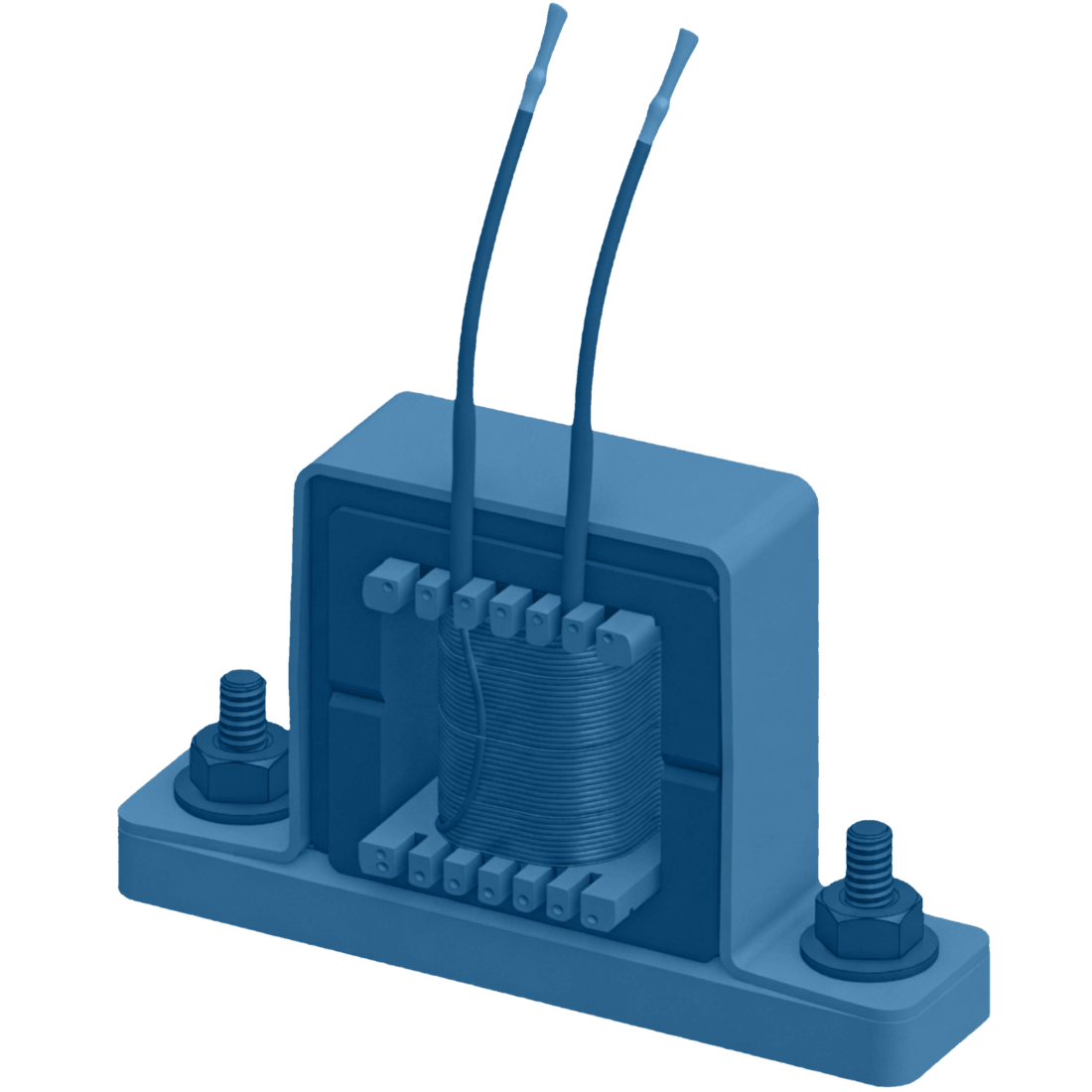
Description

How it behaves

  •  

What do Resonant Chokes aim to solve

  •  

  • Suppressing/amplifying specific frequencies
      → Tuned LC circuit match inductive and capacitive elements for a given frequency range
  • Resonant tank impedance response filter types
    → LC in series with load → band-pass
    → LC in parallel with load → band-stop (“notch”)
    → L in series, C in parallel with load → Second-order low-pass
    → C in series, L in parallel with load → Second-order high-pass
  • Filter roll-off/steepness determined by order
    → higher-order filter rolls off faster and is steeper

+ Can be used to manipulate current and voltage waveform timing
    → Soft switching: ZVS/ZCS
    → Pulse Frequency Modulation can be used to control output voltage

Voltage (RMS/peak) 800V / 900V
Current (RMS/peak) 30A / 40A
DC Resistance ~ 10mΩ
Inductance 50µH - 800µH
Q Factor* 100 - 200
Frequency ** 10kHz - 400kHz

 
* Value at resonant frequency
** High frequencies, especially above 300kHz, will limit power handling

  • Antenna tuning networks
  • LC resonators
  • Series resonant converters → LLC & CLLC
  • Parallel resonant converters → LCC
  • Quasi-resonant Dual Active Bridge

Frequently asked questions

Tell us about your project

Share your technical specifications using the form. If your project involves confidential information, simply let us know. We can arrange an NDA before discussing your application in more detail.

Share your requirements and our team will get back to you within 2 business days.

"*" indicates required fields

This field is for validation purposes and should be left unchanged.
Name*
For example: dimensions, quantities, performance, environment or prototype needs.
Get in touch