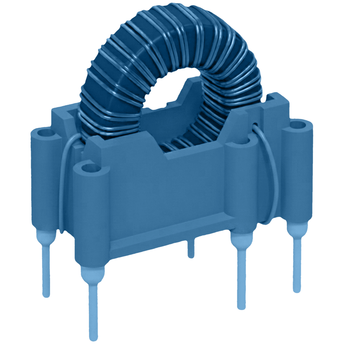
- Toroidal shape → Lower magnetic stray fields → Better EMI/EMC compliance
- Electromagnetic compatibility (EMC) with connected components/circuits
Description
How it behaves
-
When a common-mode signal is applied the current travels in the same direction through both coils → magnetic core flux weakens → impedance is low
-
When a differential-mode signal is applied the current travels in the opposite direction through the coils → magnetic core flux builds up → impedance is high
What do Differential-Mode Chokes aim to solve
-
Lower magnetic stray fields → better EMI/EMC
-
Electromagnetic compatibility (EMC) with connected components/circuits
| Voltage (RMS/peak) | 400V / 550V |
| Current (RMS/peak) | 70A / 80A |
| DC Resistance | ~10mΩ |
| Inductance | ~ 2mH |
| Q Factor * | < 10 |
| Frequency ** | 300Hz - 400kHz |
* At operating frequency (High Q at operating frequency, Low Q at noise frequency)
** High frequencies, especially above 300kHz, will limit power handling
- Current balancing of parallelised MOSFET gate signals
- Solar inverters
- Power line EMC filters
- Reducing SMPS dV/dt and dI/dt noise caused by transistor switching and input capacitor
→ Buck, Boost and Buck-Boost
Frequently asked questions
Tell us about your project
Share your technical specifications using the form. If your project involves confidential information, simply let us know. We can arrange an NDA before discussing your application in more detail.
Share your requirements and our team will get back to you within 2 business days.
"*" indicates required fields